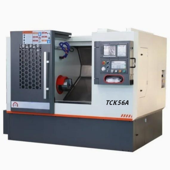

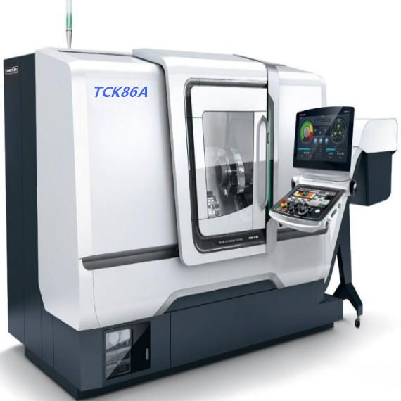
TCK86A Medium and Large Slant Bed CNC Turning Lathe Machine
Core Advantages:
1. The TCK86A series is equipped with a high-speed, high-precision, and high-rigidity shell-type spindle unit and a servo spindle motor, enabling a higher spindle speed.
2. The X and Z axes are directly driven by servo motors via flexible couplings and lead screws. The lead screws adopt a pre-stretching structure, which eliminates transmission backlash and compensates for the impact of thermal deformation. An optional gang tool configuration is available, featuring fast tool change and high positioning accuracy.
3. It is furnished with a centralized automatic lubrication device that provides timed, quantitative, and intermittent lubrication. The machine tool adopts a fully enclosed protection design, delivering excellent waterproof and chip-proof performance. In addition, the tailstock adopts servo drive and hydraulic locking, ensuring high machining stability.
- Overview
- Recommended Products
Specifications
SPECIFICATIONS | Unit | TCK86A |
Max.swing over bed | mm | 860 |
Max.swing over slide | mm | 630 |
Max.processing length | mm | 1000/1500/2000/3000/4000+ |
Max.bar capacity | mm | 90/115 |
Max.processing diameter(plate) | mm | 630 |
Spindle nose type | A2-11 | |
Spindle bore | mm | Φ104/Φ130 |
Spindle speed range | min | 1500/800 |
Spindle shift mode | Stepless | |
Spindle motor power | kw | 18.5/22 |
Chuck type | Hydraulic | |
Chuck size | Inch | 15 |
X axis rapid traverse | m/min | 12 |
Z axis rapid traverse | m/min | 15 |
X axis servo motor torque | N.m | 22 |
Z axis servo motor torque | N.m | 22 |
X axis travel | mm | 430 |
Z axis travel | mm | 1650/2150/3150/4150+ |
X/Z axis guide way type | mm | 55/65 Linear rail |
Tool post type | Horizontal 12 stations | |
Tool shank size | mm | Cylindical cutters baring tools 25/32/42/50 |
Tail stock type | Hydaulic Optional servo | |
Tailstock guide form | Hard rail | |
Tail stock quill diameter | mm | 150 |
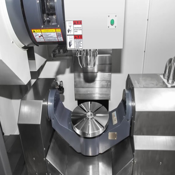
Key Components

Optional Configuration


Manufacturing Process

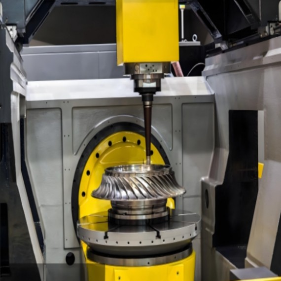
The CNC machining process starts with creating a G-code program based on the workpiece’s 3D model, defining cutting paths, speeds, and tool changes. The program is uploaded to the CNC system, which interprets instructions to control the spindle, feed axes, and tool turret. After clamping the workpiece securely with a chuck, the machine initiates automatic machining—executing turning, milling, drilling, or threading as programmed. During operation, real-time monitoring ensures precision, with coolant and chip removal systems maintaining stability. Once completed, the workpiece is inspected for accuracy, and the program is saved for future batch production.
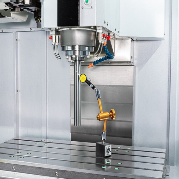
Multi-Layer Process Inspection

Laser Interferometer (Accuracy Calibration), Ball Bar (Circularity Calibration), Spindle/Motor Dynamic Balancing, Hardness Testing, Noise Testing, Machine Tool Geometric Accuracy Inspection, Lead Screw/Guide Rail Precision Inspection, Tool Changer/Machining Inspection.